Thaddeus Beier
Silicon Graphics Computer
Systems 2011 Shoreline Blvd,
Mountain View CA 94043
[thad@hammerhead.com]
http://www.hammerhead.com/thad/thad.html
Shawn Neely
[shawnn@believe.com]
A new technique is presented for the metamorphosis of one digital image into another. The approach gives the animator high-level control of the visual effect by providing natural feature-based specification and interaction. When used effectively, this technique can give the illusion that the photographed or computer generated subjects are transforming in a fluid, surrealistic, and often dramatic way. Comparisons with existing methods are drawn, and the advantages and disadvantages of each are examined. The new method is then extended to accommodate keyframed transformations between image sequences for motion image work. Several examples are illustrated with resulting images.
Keywords: Computer Animation, Interpolation, Image Processing, Shape Transformation.
Metamorphosis between two or more images over time is a useful visual technique, often used for educational or entertainment purposes. Traditional filmmaking techniques for this effect include clever cuts (such as a character exhibiting changes while running through a forest and passing behind several trees) and optical cross- dissolve, in which one image is faded out while another is simultaneously faded in (with makeup change, appliances, or object substitution). Several classic horror films illustrate the process; who could forget the hair-raising transformation of the Wolfman, or the dramatic metamorphosis from Dr. Jekyll to Mr. Hyde? This paper presents a contemporary solution to the visual transformation problem.
Taking the cutting approach to the limit gives us the technique of stop-motion animation, in which the subject is progressively transformed and photographed one frame at a time. This process can give the powerful illusion of continuous metamorphosis, but it requires much skill and is very tedious work. Moreover, stop-motion usually suffers from the problem of visual strobing by not providing the motion blur normally associated with moving film subjects. A motion-controlled variant called go-motion (in which the frame-by- frame subjects are photographed while moving) can provide the proper motion blur to create a more natural effect, but the complexity of the models, motion hardware, and required skills becomes even greater.
We can use technology in other ways to help build a metamorphosis tool. For example, we can use computer graphics to model and render images which transform over time.
One approach involves the representation of a pair of three- dimensional objects as a collection of polygons. The vertices of the first object are then displaced over time to coincide in position with corresponding vertices of the second object, with color and other attributes similarly interpolated. The chief problem with this technique is the difficulty in establishing a desirable vertex correspondence; this often imposes inconvenient constraints on the geometric representation of the objects, such as requiring the same number of polygons in each model. Even if these conditions are met, problems still arise when the topologies of the two objects differ (such as when one object has a hole through it), or when the features must move in a complex way (such as sliding along the object surface from back to front). This direct point-interpolation technique can be effective, however, for transformations in which the data correspondence and interpolation paths are simple. For example, the technique was successfully used for the interpolation of a regular grid of 3D scanned data in "Star Trek IV: The Voyage Home" [13]. Methods for automatically generating corresponding vertices or polygons for interpolation have been developed. [5][6]
Other computer graphics techniques which can be used for object metamorphosis include solid deformations [1] [12] and particle systems [10]. In each case the 3D model of the first object is transformed to have the shape and surface properties of the second model, and the resulting animation is rendered and recorded.
While three-dimensional object metamorphosis is a natural solution when both objects are easily modeled for the computer, often the complexity of the subjects makes this approach impractical. For example, many applications of the effect require transformations between complex objects such as animals. In this case it is often easier to manipulate scanned photographs of the scene using two- dimensional image processing techniques than to attempt to model and render the details of the animal's appearance for the computer.
The simplest method for changing one digital image into another is simply to cross-dissolve between them. The color of each pixel is interpolated over time from the first image value to the corresponding second image value. While this method is more flexible than the traditional optical approach (simplifying, for example, different dissolve rates in different image areas), it is still often ineffective for suggesting the actual metamorphosis from one subject to another. This may be partially due to the fact that we are accustomed to seeing this visual device used for another purpose: the linking of two shots, usually signifying a lapse of time and a change in place [7].
Another method for transforming one image into another is to use a two-dimensional "particle system" to map pixels from one image onto pixels from the second image. As the pixel tiles move over time the first image appears to disintegrate and then restructure itself into the second image. This technique is used in several video effects systems (such as the Quantel Mirage) [11].
Another transformation method involves image warping so that the original image appears to be mapped onto a regular shape such as a plane or cylinder. This technique has limited application towards the general transformations under consideration in this paper, but has the advantage of several real-time implementations for video (such as the Ampex ADO) [11]. Extensions include mapping the image onto a free-form surface; one system has even been used for real- time animation of facial images [8].
Other interesting image warps have been described by Holzmann [3] [4], Smith [14], and Wolberg[16].
We use the term "morphing" to describe the combination of generalized image warping with a cross-dissolve between image elements. The term is derived from "image metamorphosis" and should not be confused with morphological image processing operators which detect image features. Morphing is an image processing technique typically used as an animation tool for the metamorphosis from one image to another. The idea is to specify a warp that distorts the first image into the second. Its inverse will distort the second image into the first. As the metamorphosis proceeds, the first image is gradually distorted and is faded out, while the second image starts out totally distorted toward the first and is faded in. Thus, the early images in the sequence are much like the first source image. The middle image of the sequence is the average of the first source image distorted halfway toward the second one and the second source image distorted halfway back toward the first one. The last images in the sequence are similar to the second source image. The middle image is key; if it looks good then probably the entire animated sequence will look good. For morphs between faces, the middle image often looks strikingly life-like, like a real person, but clearly it is neither the person in the first nor second source images.
The morph process consists of warping two images so that they have the same "shape", and then cross dissolving the resulting images. Cross-dissolving is simple; the major problem is how to warp an image.
Morphing has been used as a computer graphics technique for at least a decade. Tom Brigham used a form of morphing in experimental art at NYIT in the early 1980's. Industrial Light and Magic used morphing for cinematic special effects in Willow and Indiana Jones and the Last Crusade. All of these examples are given in Wolberg's excellent treatise on the subject[15].
Wolberg's book effectively covers the fundamentals of digital image warping, culminating in a mesh warping technique which uses spline mapping in two dimensions. This technique is both fast and intuitive; efficient algorithms exist for computing the mapping of each pixel from the control grid, and a rubber-sheet mental model works effectively for predicting the distortion behavior. It will be compared to our technique in detail below.
We now introduce a new technique for morphing based upon fields of influence surrounding two-dimensional control primitives. We call this approach "field morphing" but will often simply abbreviate to "morphing" for the remainder of this paper.
There are two ways to warp an image [15]. The first, called forward mapping, scans through the source image pixel by pixel, and copies them to the appropriate place in the destination image. The second, reverse mapping, goes through the destination image pixel by pixel, and samples the correct pixel from the source image. The most important feature of inverse mapping is that every pixel in the destination image gets set to something appropriate. In the forward mapping case, some pixels in the destination might not get painted, and would have to be interpolated. We calculate the image deformation as a reverse mapping. The problem can be stated "Which pixel coordinate in the source image do we sample for each pixel in the destination image?"
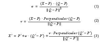
A pair of lines (one defined relative to the source image, the other defined relative to the destination image) defines a mapping from one image to the other. (In this and all other algorithms and equations, pixel coordinates are BOLD UPPERCASE ITALICS, lines are specified by pairs of pixel coordinates(PQ), scalars are bold lowercase italics, and primed variables (X', u') are values defined relative to the source image. We use the term line to mean a directed line segment.)
A pair of corresponding lines in the source and destination images defines a coordinate mapping from the destination image pixel coordinate X to the source image pixel coordinate X' such that for a line PQ in the destination image and P'Q' in the source image.
where Perpendicular() returns the vector perpendicular to, and the same length as, the input vector. (There are two perpendicular vectors; either the left or right one can be used, as long as it is consistently used throughout.)
The value u is the position along the line, and v is the distance from the line. The value u goes from 0 to 1 as the pixel moves from P to Q, and is less than 0 or greater than 1 outside that range. The value for v is the perpendicular distance in pixels from the line. If there is just one line pair, the transformation of the image proceeds as follows:
For each pixel X in the destination image
        find the corresponding u,v
        find the X' in the source image for that u,v
        destinationImage(X) = sourceImage(X')
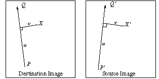
Figure 1: Single line pair
In Figure 1, X' is the location to sample the source image for the pixel at X in the destination image. The location is at a distance v (the distance from the line to the pixel in the source image) from the line P'Q', and at a proportion u along that line.
The algorithm transforms each pixel coordinate by a rotation, translation, and/or a scale, thereby transforming the whole image. All of the pixels along the line in the source image are copied on top of the line in the destination image. Because the u coordinate is normalized by the length of the line, and the v coordinate is not (it is always distance in pixels), the images is scaled along the direction of the lines by the ratio of the lengths of the lines. The scale is only along the direction of the line. We have tried scaling the v coordinate by the length of the line, so that the scaling is always uniform, but found that the given formulation is more useful.
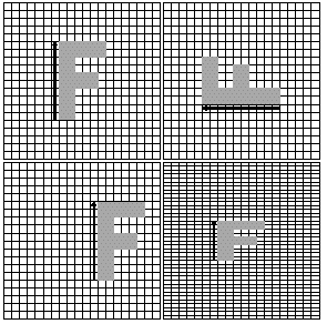
Figure 2: Single line pair examples
The figure on the upper left is the original image. The line is rotated in the upper right image, translated in the lower left image, and scaled in the lower right image, performing the corresponding transformations to the image.
It is possible to get a pure rotation of an image if the two lines are the same length. A pair of lines that are the same length and orientation but different positions specifies a translation of an image. All transformations based on a single line pair are affine, but not all affine transformations are possible. In particular, uniform scales and shears are not possible to specify.
Multiple pairs of lines specify more complex transformations. A weighting of the coordinate transformations for each line is performed. A position Xi' is calculated for each pair of lines. The displacement Di = Xi' - X is the difference between the pixel location in the source and destination images, and a weighted average of those displacements is calculated. The weight is determined by the distance from X to the line. This average displacement is added to the current pixel location X to determine the position X' to sample in the source image. The single line case falls out as a special case of the multiple line case, assuming the weight never goes to zero anywhere in the image. The weight assigned to each line should be strongest when the pixel is exactly on the line, and weaker the further the pixel is from it. The equation we use is
![]()
where length is the length of a line, dist is the distance from the pixel to the line, and a, b, and p are constants that can be used to change the relative effect of the lines.
If a is barely greater than zero, then if the distance from the line to the pixel is zero, the strength is nearly infinite. With this value for a, the user knows that pixels on the line will go exactly where he wants them. Values larger than that will yield a more smooth warping, but with less precise control. The variable b determines how the relative strength of different lines falls off with distance. If it is large, then every pixel will be affected only by the line nearest it. If b is zero, then each pixel will be affected by all lines equally. Values of b in the range [0.5, 2] are the most useful. The value of p is typically in the range [0, 1]; if it is zero, then all lines have the same weight, if it is one, then longer lines have a greater relative weight than shorter lines.
The multiple line algorithm is as follows:
For each pixel X in the destination
        DSUM = (0,0)
        weightsum = 0
        For each line Pi Qi
                calculate u,v based on Pi Qi
                calculate X'i based on u,v       and Pi'Qi'
                calculate displacement Di = Xi' - Xi for this line
                dist = shortest distance from X to Pi Qi
                weight = (lengthp / (a + dist))b
                DSUM += Di *    weight
                weightsum += weight
        X' = X + DSUM / weightsum
        destinationImage(X) = sourceImage(X')
Note that because these "lines" are directed line segments, the distance from a line to a point is abs(v) if 0 < u < 1, the distance from P to the point if u < 0, and the distance from Q to the point if u > 1.
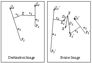
Figure 3: Multiple line pairs
In the above figure, X' is the location to sample the source image for the pixel at X in the destination image. That location is a weighted average of the two pixel locations X1' and X2', computed with respect to the first and second line pair, respectively.
If the value a is set to zero there is an undefined result if two lines cross. Each line will have an infinite weight at the intersection point. We quote the line from Ghostbusters: "Don't cross the streams. Why? It would be bad." This gets the point across, and in practice does not seem to be too much of a limitation. The animator's mental model when working with the program is that each line has a field of influence around it, and will force pixels near it to stay in the corresponding position relative to the line as the line animates. The closer the pixels are to a line, the more closely they follow the motion of that line, regardless of the motion of other lines. This mental model gives the animator a good intuitive feel for what will happen as he designs a metamorphosis.
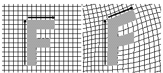
Figure 4: Multiple line pair example
With two or more lines, the transformation is not simple. The figure on the left is the original image, it is distorted by rotating the line above the F around its first point. The whole image is distorted by this transformation. It is still not possible to do a uniform scale or a shear with multiple lines. Almost any pair of lines results in a non- affine transformation. Still, it is fairly obvious to the user what happens when lines are added and moved. Pixels near the lines are moved along with the lines, pixels equally far away from two lines are influenced by both of them.
A morph operation blends between two images, I0 and I1. To do this, we define corresponding lines in I0 and I1. Each intermediate frame I of the metamorphosis is defined by creating a new set of line segments by interpolating the lines from their positions in I0 to the positions in I1. Both images I0 and I1 are distorted toward the position of the lines in I. These two resulting images are cross- dissolved throughout the metamorphosis, so that at the beginning, the image is completely I0 (undistorted because we have not yet begun to interpolate away from the line positions associated with I0). Halfway through the metamorphosis it is halfway between I0 and I1, and finally at the end it is completely I1. Note that there is a chance that in some of the intermediate frames, two lines may cross even if they did not cross in the source images.
We have used two different ways of interpolating the lines. The first way is just to interpolate the endpoints of each line. The second way is to interpolate the center position and orientation of each line, and interpolate the length of each line. In the first case, a rotating line would shrink in the middle of the metamorphosis. On the other hand, the second case is not very obvious to the user, who might be surprised by how the lines interpolate. In any case, letting the user see the interpolated position helps him design a good set of beginning and end positions.
For video-resolution images (720x486 pixels) with 100 line pairs, this algorithm takes about 2 minutes per frame on a SGI 4D25. The runtime is proportional to the number of lines times the number of pixels in the image. For interactive placement of the lines, low resolution images are typically used. As is usually the case with any computer animation, the interactive design time is the dominant time; it often takes 10 times as long to design a metamorphosis than to compute the final frames.
This technique has one big advantage over the mesh warping technique described in Wolberg's book[15]: it is much more expressive. The only positions that are used in the algorithm are ones the animator explicitly created. For example, when morphing two faces, the animator might draw line segments down the middle of the nose, across the eyes, along the eyebrows, down the edges of the cheeks, and along the hairline. Everything that is specified is moved exactly as the animator wants them moved, and everything else is blended smoothly based on those positions. Adding new line segments increases control in that area without affecting things too much everywhere else.
This feature-based approach contrasts with the mesh warping technique. In the simplest version of that algorithm, the animator must specify in advance how many control points to use to control the image. The animator must then take those given points and move them to the correct locations. Points left unmodified by mistake or points for which the animator could not find an associating feature are still used by the warping algorithm. Often the animator will find that he does not have enough control in some places and too much in others. Every point exerts the same amount of influence as each of the other points. Often the features that the animator is trying to match are diagonal, whereas the mesh vertices start out vertical and horizontal, and it is difficult for the animator to decide which mesh vertices should be put along the diagonal line.
We have found that trying to position dozens of mesh points around is like trying to push a rope; something is always forced where you don't want it to go. With our technique the control of the line segments is very natural. Moving a line around has a very predictable effect. Extensions of the mesh warping technique to allow refinement of the mesh would make that technique much more expressive and useful[2].
Another problem with the spline mesh technique is that the two-pass algorithm breaks down for large rotational distortions (bottleneck problem)[14][15]. The intermediate image in the two pass algorithm might be distorted to such an extent that information is lost. It is possible do mesh warping with a one-pass algorithm that would avoid this problem.
The two biggest disadvantages of our feature-based technique are speed and control. Because it is global, all line segments need to be referenced for every pixel. This contrasts with the spline mesh, which can have local control (usually the 16 spline points nearest the pixel need be considered).
Between the lines, sometimes unexpected interpolations are generated. The algorithm tries to guess what should happen far away from the line segments; sometimes it makes a mistake. This problem usually manifests itself as a "ghost" of a part of the image showing up in some unrelated part of the interpolated image, caused by some unforeseen combination of the specified line segments. A debugging tool can be useful in this case, in which the user can point to a pixel in the interpolated image and the source pixel is displayed, showing where that pixel originated. Using this information, the animator can usually move a line or add a new one to fix the problem.
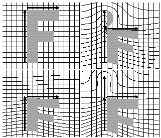
Figure 6: Ghostbusting
In Figure 6, the top left image is the original. Moving the horizontal line down creates a ghost above the line, that is made from pixels copied from the top edge of the F. The bottom left image shows one fix, shrinking the vertical line to match the horizontal one. If the vertical line must maintain its length for some other reason, then the ghost can be eliminated by breaking the vertical line into two parts, as shown on the lower right.
It is often useful to morph between two sequences of live action, rather than just two still images. The morph technique can easily be extended to apply to this problem. Instead of just marking corresponding features in the two images, there needs to be a set of line segments at key frames for each sequence of images. These sets of segments are interpolated to get the two sets for a particular frame, and then the above two-image metamorphosis is performed on the two frames, one from each strip of live action. This creates much more work for the animator, because instead of marking features in just two images he will need to mark features in many key frames in two sequences of live action. For example, in a transition between two moving faces, the animator might have to draw a line down the nose in each of 10 keyframes in both sequences, requiring 20 individual line segments. However, the increase in realism of metamorphosis of live action compared to still images is dramatic, and worth the effort. The sequences in the Michael Jackson video, Black or White, were done this way.
We have been using this algorithm at Pacific Data Images for the last two years. The first projects involved interpolation of still images. Now, almost all of the projects involve morphing of live- action sequences.
While the program is straightforward and fun to use, it still requires a lot of work from the animator. The first project using the tool, (the Plymouth Voyager metamorphosis), involved morphs between nine pairs of still images. It took three animator-weeks to complete the project. While it was very quick to get a good initial approximation of a transition, the final tweaking took the majority of the time. Of course, it was the first experience any of us had with the tool, so there was some learning time in those three animator-weeks. Also, a large amount of time was spent doing traditional special effects work on top of the morph feature matching. For example, the images had to be extracted from the background (using a digital paint program), some color balancing needed to be done, and the foreground elements had to be separated form each other (more painting). These elements were morphed separately, then matted together. On current morph production jobs at PDI, we estimate that about 20-40 percent of the time is spent doing the actual metamorphosis design, while the rest of the time is used doing traditional special effects.
Tom Brigham of the New York Institute of Technology deserves credit for introducing us to the concept of morph. The magicians at Industrial Light and Magic took the idea to a new level of quality in several feature films, and provided inspiration for this work. Jamie Dixon at PDI was a driving force behind the creation of the tools, and the rest of the animators at PDI have been the best users that we can imagine. The great animation created with this program is mostly their work, not ours. Finally, Carl Rosendahl, Glenn Entis, and Richard Chuang deserve credit for making Pacific Data Images the creative, fun environment where great new things can happen, and for allowing us to publish details of a very profitable algorithm.
[1] Barr, A.H., Global and Local Deformations of Solid Primitives. In "Proc. SIGGRAPH `84" (Minneapolis, July 23-27, 1984). Published as "Computer Graphics", 18(3) (July 1984), pp. 21-30.
[2] Forsey, D. R., Bartels, R. H., Hierarchical B-Spline Refinement. In "Proc. SIGGRAPH `88" (Atlanta, August 1-5, 1988). Published as "Computer Graphics", 22(4) (August 1988), pp. 205-211
[3] Holzmann, G.J., PICO --- A Picture Editor. "AT&T Technical Journal", 66(2) (March/April 1987), pp. 2-13.
[4] Holzmann, G.J., "Beyond Photography: The Digital Darkroom". Prentice Hall, 1988.
[5] Kaul, A., Rossignac, J., "Solid-Interpolating Deformations: Constructions and Animation of PIPs," Proceedings of EUROGRAPHICS `91, September 1991, pp. 493-505
[6] Kent, J.,Parent, R., Carlson, W. "Establishing Correspondences by Topological Merging: A New Approach to 3-D Shape Transformation", Proceedings of Graphics Interface `91, June 1991, pp. 271-278
[7] Oakley, V., "Dictionary of Film and Television Terms". Barnes & Noble Books, 1983.
[8] Oka, M., Tsutsui, K., Akio, O., Yoshitaka, K., Takashi, T., Real- Time Manipulation of Texture-Mapped Surfaces. In "Proc. SIGGRAPH `87" (Anaheim, July 27-31, 1987). Published as "Computer Graphics", 21(4) (July 1987), pp. 181-188.
[9]Overveld, C.W.A.M. Van A Technique for Motion Specification."Visual Computer". March 1990
[10] Reeves, W.T., Particle Systems: A Technique for Modeling a Class of Fuzzy Objects. "ACM Transactions on Graphics", 2(2) (April 1983). (Reprinted in "Proc. SIGGRAPH `83" (Detroit, July 25-29, 1983). Published as "Computer Graphics", 17(3) (July 1983), pp. 359-376.)
[11] Rosenfeld, M., Special Effects Production with Computer Graphics and Video Techniques. In "SIGGRAPH `87 Course Notes #8 - Special Effects with Computer Graphics" (Anaheim, July 27- 31, 1987).
[12] Sederberg, T.W. and Parry, S.R., Free-Form Deformation of Solid Geometric Models. In "Proc. SIGGRAPH `86" (Dallas, August 18-22, 1986). Published as "Computer Graphics", 20(4) (August 1986), pp. 151-160.
[13] Shay, J.D., Humpback to the Future. "Cinefex 29" (February 1987), pp. 4-19.
[14] Smith, A.R., Planar 2-Pass Texture Mapping and Warping. In "Proc. SIGGRAPH `87" (Anaheim, July 27-31, 1987). Published as "Computer Graphics", 21(4) (July 1987), pp. 263-272.
[15] Wolberg, G., "Digital Image Warping". IEEE Computer Society Press, 1990.
[16] Wolberg, G., Skeleton Based Image Warping, "Visual Computer", Volume 5, Number 1/2, March 1989. pp 95-108