The general idea of the ras_track program is that witness points are tracked, and these witness points moving over time determine how the whole image moves. These witness points are features in the image that are easy to locate and track as they move. If there is enough contrast in the witness points, the ras_track program has a correlation-based tracker that will do the tracking automatically. Once these points are tracked, this 2D screen-space tracking information can be used to calculate a 2D image transformation, or 3D camera or object transformations.
There are several options that can be specified on the command line. These are as follows (this can be printed by typing ras_track -):
usage:  ras_track [track.mp] [-source prefix] [-o output_prefix] [-match other_track.mp]
                  [-a minframe] [-z maxframe] [-s step]
                  [-inverse] [-integer] [-fast] [-wrap]
                  [-translate_x] [-translate_y] [-rotate] [-scale] [-cineon]
which:  calculates translate, rotate, and scale paramters to steady images
where:  track.mp       is the multipath file that stores tracking information
         prefix         is the root name of the raster images
  The rest of these arguments only apply to the batch frame process
        output_prefix  specifies the output prefix, for batch computation
        other_track.mp is a different track file.  The output frames are tracked to
                       the specified track file
        -translate_x   don't change the x translation value
        -translate_y   don't change the y translation value
        -rotate        don't change the rotation value
        -scale         don't change the scale value
        -integer       [obsolete] only do integer tracking
        -wrap          wrap when translating images
        -fast          use fast bilinear interpolation
        -cineon        output cineon format images
None of these arguments need be specified, they can be all set interactively, but they are listed here to describe what they do.
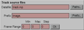
The first argument is thetrack.mp datafile. Its suffix is .mp, signifying that it is a "multipath" file. A Hammerhead multipath file contains a list of paths. A path can contain any number of named constants, and any number of named tracks. A track is variable that varies over time. The multipath file contains a path for each of the tracked points, a path for image motion, paths for camera and object transformations, and other bookeeping paths.
Theprefix argument specifies the prefix of the image files. Each image file must be of the format prefix###[.ext] where prefix is any text string, ### is a frame number, possibly prefixed by 0's, and .ext is an optional extension. For example, if you have pictures named heli.3.rgb, heli.4.rgb ... heli.299.rgb then the prefix is heli. Note the period at the end of the prefix. If you don't include that, ras_track will be helpless to find your images.
The format for the images can be SGI RGB (8 or 16 bit), Cineon (3 or 4 channel), TIFF (8 or 16 bit), or Wavefront RLA (8 bit only).
The -wrap flag causes the image to wrap as you are steadying it. This is useful if you want to steady a sequence, process it somehow, and then put it back where it was, without losing pixels off the edge. Naturally, this only works for translation.
The output_prefix is the prefix of the output pictures. The output of the tracking is a series of adjusted pictures. By specifying an output prefix, you are also indicating to the tracking program that you want it to create the output images in batch mode, and it will immediately start to create pictures.
The minframe, maxframe, and step parameters define the frame range of the sequence. minframe is the first frame of the sequence, maxframe is the last frame, and step is the interval between frames.
The -inverse flag specifies that the inverse operation is to be performed. The standard operation that ras_track performs is to steady a shot. The inverse of that would be to track another shot to the unsteady plate that the tracking was defined from. You would use the -source parameter and the -inverse parameters together, most of the time.
The -integer flag specifies that the image transformation is done to integer precision. This is sometimes done to limit the amount of blurring that happens when an image is transformed. The default image transformation code in ras_track is really quite good, though, and while you never want to go down a generation more than you have to, you can usually get away with it.
The -fast parameter specifies that the image transformation be done with a simple bilinear transformation, rather than using the good negative lobe filter that it used by default. It is about 6 times as fast, but is significantly blurrier in most cases.
The -translate_x, -translate_y, -rotate and -scale parameters are used to limit the images transformation. If you specify the -rotate flag, then the rotation calculated would be fixed at 0 all the time.
The datafile is the multipath file described above. The prefix is the prefix described above. The Paths... and Prefix... buttons bring up browsers to select these files by browsing through directories.
For this, and every other interface panel, you can get help for any button by hitting the right mouse button over the interface widget that you are confused about.
Once you specify a prefix, the ras_track program will look for all files that match that prefix, and fill in the Min, Max, and Step entries that correspond to the files found. Once a valid Datafile and Prefix are entered, the Ok button is activated, indicating that you can proceed to the main interface panel and begin tracking. Hitting Ok brings up the image, and closes this source panel.
There are several sub-panels that come up, but the main panel controls everything.
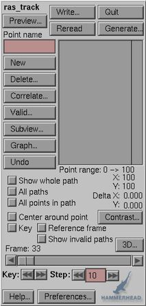
To start, hit the New button. Now, move to the image, and click on a good looking feature with the left mouse button to begin tracking it. Each point has a name, this is the name of the path in the multipath file. The position of this point is specified at key frames, and these are set by interactively positioning the cursor over the feature in a frame. Points are moved with the middle mouse button. In general, in Hammerhead programs, the left mouse button picks or creates things, and the middle mouse button moves them. One way to remember this is "middle" and "move" both start with "m".
The current point is green, by default, and other points are red. These can be changed by the Preferences panel. A point that has a key is a heavy mark, if there is no key at this frame, it is a light +. Names for points are defined, by default, as p0, p1, p2 ... . The name of the current point can be changed by typing a new name into the Point Name window.
A point can be deleted by hitting the Delete key. Now, there is no Undo yet, so be careful about hitting this key.
The Correlate button brings up the Correlate panel. It allows you to use correlation to track the point automatically. Correlation should be used, as opposed to keyframing, both because it is easier, and potentially more accurate.
You can show the whole current path, as it moves through time, by hitting the Show whole path button.
The Center around point button causes the image to be always centered about the current track point. This can be confusing, because once this is set you cannot scroll the image, and it appears to be broken, probably trying to move the image should unset this button.
The Show whole path button displays the motion of the point throughout its existence. The All Paths button does the same thing for every point that is valid at the current frame. The All points in path button shows little tick marks at every key point in the path.
The Key button is critical. Whenever a point is position, a key
in the spline that determines its motion over time is created. Hitting
the key button toggles whether there is a key at the current frame
or not. The keyboard shortcut for this is the letter k.
When a point is a key, then it is shown with a little key icon on the
Valid panel.
As mentioned before, the power of the ras_track program comes from its ability to use correlation to automatically track points. If the image changes dramatically, however, it will be impossible to use correlation to track a point from the beginning to the end of the sequence. To solve this problem, it is possible to create an extra Reference Frame in the middle of the sequence. Then, for subsequent frames, the correlation is done with respect to this frame, rather than back to the beginning of the sequence. Reference frames show up a little lock in the image and in the Valid window.
The Valid... button brings up the validity panel.
The Graph... button brings up a graphing panel, to show the shape of the generated camera, object, and 2D motion curves over time. Within the graph panel, you can smooth the curves, as well.
The Subviewport button brings up the Subviewport panel, which can be used to limit the size of the image for faster reading, calculation, and interaction.
The 3D button is for 3D camera and object tracking. It opens up the 3D camera tracking panel, and once you have a valid camera you can open a object tracking panel.
The Contrast button brings up a contrast adjustment panel. This can be used to help you see features better; although it has no effect on the either the correlation tracking or in the generation of steady frames.
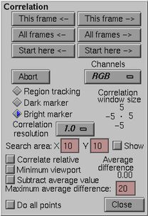
The correlate panel allows you to let the computer track points. Tracking points can be done manually, but it is somewhat inaccurate and slow. Correlation for tracking is faster and more accurate, but only works if there are features that correlate well. These features would have reasonably high contrast, and are clearly different from the area around them.
You should first track very roughly, to give the correlator a good starting point. A good starting point may be to hand track every 20 frames, where accuracy is not that important. Then, allow the computer to refine that track using correlation.
The way that correlation works is that the current frame is compared to the reference frame. The box enclosed by the correlation window in the current frame is slid over the reference frame.An error value is determined, which is the average difference in pixel value between the current frame and the reference frame within the correlation window. Whatever position had the smallest error is the correct, correlated position. This sliding happens at .2 (that's 1/5th) of a pixel resolution, giving substantially more accuracy than one could hope to get by hand.
When the correlate window is popped up, the image screen displays a box. This is the correlate window for the current point. You can drag the corners of the window to make the correlate region bigger or smaller, or to enclose only the parts of the feature that you want. Making it bigger will potentially make it more accurate, but will make the correlation run more slowly. The size of the window is displayed in the upper right corner of the correlate panel. It is sometimes inconvenient to have the correlate window open, because it's easy to move the box corners instead of the center of the box, so keep the correlate window closed when it's not being used.
There are six buttons that determine which frames should be tracked. In general, you can correlate with respect to earlier or later frames. A typical example would be as follows: You have a sequence of frames named unsteady.0.rgb up to unsteady.99.rgb. If you hit the All frames <- button, then it will correlate frame 1 to frame 0, frame 2 to frame 0, ... up to frame 99. The <- means that we are looking back to a previous frame to correlate from. You can use the correlation to just track the current frame, all the frames, or from the current frame until the end of the sequence.
Any time that the correlation is running, you can hit the Abort button. This will terminate the tracking at the current frame.
The amount to slide the correlation window in the X and Y directions is determined by the Search Area values. Setting larger values here allows the correlation to look further for a match, but makes the program run more slowly. If your rough hand tracking is not accurate at all, you may need to increase these from the default values of +/- 10 pixels.
The Minimum viewport button is a real time-saver, but is a little confusing. The way that ras_track works is that it compares the correlation window of the reference frame to the current frame. The pixels that are used from the current frame are those that are centered on the interpolated position, and extend to encompass the size of the correlation window, plus the size of the search area on both sides. Therefore, only this small window need be read to do the correlation; which can save a lot of time on a big image. Only that small window will be read and displayed.
The Correlate relative button is used to specify that correlation should look at the previous frame, rather than back to the previous reference frame (or the first frame of the sequence, if there are no reference frames). This is necessary if the image is changing dramatically. Say that the image sequence is a helicopter shot that goes from 1 mile away from a building up to a window. Clearly, there will be no feature that would look at all the same in the first and last frames, and every feature will be changing in size dramatically during the sequence. But, each frame will change only a little bit from the previous frame, so frame-to-frame correlation will work well. The reason that Correlate relative is off by default, and should be off whenever possible, is that small random errors will accumulate frame-to-frame; this button is really a last resort.
The Average difference display shows the above-described error. The Maximum average difference is the maximum error allowed. If that error is exceeded, the program beeps and halts. This is a signal that something is wrong. Sometimes a feature becomes obscured, or it goes out of frame, or changes in some other way. The solutions are to either change the correlate window, add a new reference frame, or just increase the maximum average difference value. The default value of 20 is probably slightly on the low side.
The radio button controls the type of tracking. The most common type is Regiontracking which uses correlation. For certain cases you might be able to do one of the two kinds of marker tracking, Dark marker or Bright marker. Marker tracking works by first finding the darkest or lightest 10 percent of the pixels within the tracking box, then finding the centroid of the largest connected region of those pixels. Because of this, the tracking box should be about three or four times as wide as the marker, so that the 10 percent corresponds pretty closely to just the marker and not the background. When marker tracking works, it is much faster and somewhat more accurate than correlation tracking; so use it if you can.
The Channels popup menu controls which channels should be used
to do the correlation or marker tracking. Restricting the tracker
to just one channel makes it run faster, and could be more accurate if
one of the channels has less noise than the others.
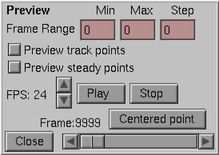
The Preview panel allows you to view the motion of the track points. The track points are displayed in real time; you can use the slider to drag back and forth through the track points. Unfortunately, the images themselves are not visible in Preview, because that would take way too much memory.
The track points after steadying can be viewed as well, to see how steady the final motion is. The transformation generated in the Generate panel is used to transform all the track points. They should stay still, or move smoothly, as the preview plays back. If they don't, then your output frames will not be steady either; you must find out what went wrong and fix it. Probably one of your track points is not staying on the feature, or you've tracked points on different planes and there is no affine transformation that steadies the points.
If the Show camera tracking or Show object tracking buttons are toggled on their respective panels, then these computed screen positions are displayed as well.
The FPS specifies the frames per second for the playback.
The Centered point button causes a small preview window to be generated. Each frame is centered, to subpixel accuracy, around the track point; so that if the 2D tracking is correct, the image will be perfectly stable within the small preview window. This option has been known to dump core on occasion, so you should probably Save before you do this.
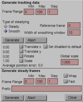
This, along with the correlate panel are the key interfaces to the program. Generate establishes how the track points are used to steady the shot, and optionally creates the steadied frames. The basic idea is that the motion of the track points can be approximated by a translation, rotation, and scale applied to each frame of the image. The best translate, rotate, and scale are calculated for each frame.
The second type is smoothing. In this type of steadying, each frame is steadied with respect to a moving average of the frames on either side of it. This takes out bumps and wiggles in the camera motion, while still allowing the camera to move substantially -- that is -- short term wiggles are smoothed out, while slow camera motion is preserved. We've had great success applying smoothing to bumpy helicopter shots, for example. For this mode, the size of this moving average window is set in the text input widget next to it. Choosing a larger number smooths out longer and longer camera moves, but causes larger excursions from the center. Values of 10 to 30 frames are probably reasonable first guesses
Each parameter can be turned on or off. If it is off, then the calculation of the best fit transformation proceeds with that value set to either the default (0 for the translations and rotation, 1 for scale.) or will be left unchanged, depending on what the state of the Set disabled to default toggle. Almost certainly you want to leave the scale parameter off when smoothing motion, as it will change the size of the image.
Once you have selected the type of steadying you want, and which parameters you want to allow to be optimized for, hit the top Generate button to begin the calculation. The Average Position Error value that is displayed shows how good a fit is obtainable given the track data. It is easy to see that not every arrangement of points is matchable, given just a translate, rotate, and uniform scale transformation. The average distance in pixels from the best-fit transformation, and the actual location of the track points, is the Average Position Error. Values of less than 1 show a very good fit, values greater than 5 should be a sign that something is amiss.
The program currently uses a new, very fast algorithm for calculating these values. However, I'm not completely sure that it works in all cases, so the Old-style toggle will use the old, slower algorithm.
The Global Scale value scales up the image by a constant amount. This will keep the edge of the image from showing after it has been transformed. Say the image is 1000 pixels across, and the maximum translation was 10 pixels. A global scale of (1 + 10/500) or 1.02 will blow up the picture enough so that you never see the edge.
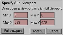
The subviewport panel allows the user to specify a subviewport, an image smaller than the whole image. These subviewports will read in and display faster than the whole image, in proportion to the ratio of the number of pixels in the whole image and the subviewport. This can be particularly useful will film resolution images. The subviewport can be specified by dragging open a box in the image, or by typing values into the boxes. Currently there is a bug with subviewports and camera and object tracking; you must ensure that you are using the full viewport when doing any 3D tracking!
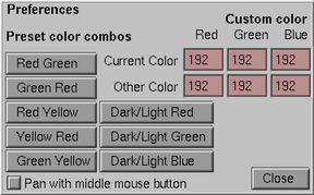
The preview panel is used to specify the color of the points. Several canned choices are available, and colors can be typed in directly in the text input windows.

The valid panel is used to control which frames a point is valid, and on which frames it is not. If a tracked point goes out of frame, or it becomes obscured by another object, it should be marked as invalid in that interval.
Clicking in the valid panel on an interval between keys causes that interval's validity to be toggled. A key frame shows up as a little key symbol, unless it is a reference frame; in that case it is shown as a lock. Invalid regions are shown as crosshatched red lines. Keys are always valid, and cannot be made otherwise. By default, the frames between the first frame of the sequence and the first key are invalid, as are the frames after the last key and the end of the sequence.
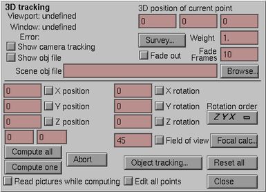
This panel allows 3D camera tracking. You can track camera position, orientation, and field-of-view. To do the 3D camera tracking, it is imperative that the viewport and window parameters be specified on the command line, as -V x0 y0 x1 y1 -W x0 y0 x1 y1. The viewport parameters are the size of the image, so if your pictures are 640 x 480, the viewport is 0 0 639 479. Typically, for square pixels, the window parameters are -1, -aspect, 1, aspect where aspect is the height of the picture divided by the width. In this case, it would be -1, -.75, 1, .75. These parameters can be specified in your environment, as well, by putting the following commands in your .cshrc file
setenv viewport "0 0 639 479"
setenv window "-1 -.75 1 .75"
Camera tracking requires at very least 4 points to be known, where more points will give you better results. For each track point, input the 3D position of the point in the upper right text input windows. ras_track assumes that the coordinate space is right handed, with positive z coming out of the screen. Enter your values accordingly. Probably future versions of the program will enable you to specify some other coordinate systems.
Type in a reasonable guess for camera parameters for the first frame of the sequence. This will serve as an initial estimate for the program. Now, turn on the boxes for the parameters that you want solved for. This may be all of them, but if you know what some of them are (say, that the camera is always vertical, so that the roll is always zero) you should leave those parameters disabled.
Hitting the Compute one button will solve the camera parameters for the current frame. Hitting Compute all will compute all the frames.
Hitting Abort will stop the computation immediately.
The Error: value is the sum of the squares of the differences in position from the hand-tracked screen positions and the calculated 3D position with the current transformations. Probably this should be replaced with the average error.
The Show camera tracking toggle will draw the computed screen coordinates of the track points using the current camera transformation. If the tracking is good, these will be very close to the points that you tracked in 2D. If they are not, then something is amiss.
The Edit all points toggle causes any input to the camera parameter boxes to be copied to every frame of the sequence. This is useful for setting every frame's field-of-view angle to the same value, for instance, but it's also a good way to destroy hours of work; so be careful.
The Reset all button deletes the camera information from every frame but the current one. It's the only way to start over fresh, if you've changed some of the 3D point positions, say. It brings up a dialog to make sure that you really want to do this.
The Weight of current point parameter defaults to 1 for all points, causing them all to be weighted equally. If you have a point that you need to track perfectly, though, then you can set the weight of that point to be higher than for the rest of them. This might, say, be where a characters feet are on the ground, so that even if the rest of the tracking is slightly off, the character will stay still on the floor.
The Rotation order popup menu allows selection of one of 6 rotation orders. The default is Y X Z, which is a reasonable choice, as it matches the order of operations on a camera tripod. If your rotations don't match what you'd expect, but the Error value is small, then probably your rotations order is wrong.
The Fade out toggle and Fade Frames entry determine how to treat points that are about to be come invalid, or have just recently become valid. By default, all valid points are treated equally, but if this button is toggled, then the influence of a newly valid point fades up as it becomes valid.
The Object tracking... button brings up the Object tracking panel.
The Survey... button brings up the Survey panel; for calculating the 3D positions of the track points.
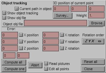
This panel allows 3D object tracking. You can track object position and orientation. You cannot, as yet, track the object scale. To do the 3D object tracking, it is imperative that there be a valid camera defined, that tracks the scene. For simple scenes, you might just specify a camera position and orientation of 0,0,0, but you'll have to come up with a reasonably accurate field-of-view angle in the camera tracking window if you want the object tracking to work.
Object tracking requires at very least 4 points to be known. For each track point, input the 3D position of the point in the upper right text input windows. ras_track assumes that the coordinate space is right handed, with positive z coming out of the screen. Enter your values accordingly. Probably future versions of the program will enable you to specify some other coordinate systems.
Each point can be part of the "object" or can be used to define the camera position. Hitting the Current path in object toggle specifies that this point is to be used in the object position calculation. (Sometimes, when trying to calculate a camera with fewer points than usual (if you think some of your positions are inaccurate, say) I've specified points as part of the object. This removes them from the camera position calculation. This is a hack, of course, but it works).
Type in a reasonable guess for object transformation parameters for the first frame of the sequence. This will serve as an initial estimate for the program. Now, turn on the boxes for the parameters that you want solved for.
Hitting the Compute one button will solve the camera parameters for the current frame. Hitting Compute all will compute all the frames.
Hitting Abort will stop the computation immediately.
The Error: value is the sum of the squares of the differences in position from the hand-tracked screen positions and the calculated 3D position with the current transformations. Probably this should be replaced with the average error.
The Show object tracking button will draw the computed screen coordinates of the track points using the current camera transformation. If the tracking is good, these will be very close to the points that you tracked in 2D. If they are not, then something is amiss.
The Read Pictures toggle will read each picture as it is computing. This slows the program considerably, especially for large images, so don't leave it on if you don't need it.
The Edit all points toggle causes any input to the camera parameter boxes to be copied to every frame of the sequence. This is useful for setting every frame's field-of-view angle to the same value, for instance, but it's also a good way to destroy hours of work; so be careful.
The Reset all button deletes the object transformation information from every frame but the current one. It's the only way to start over fresh, if you've changed some of the 3D point positions, say. It brings up a dialog to make sure that you really want to do this.
The Weight of current point parameter defaults to 1 for all points, causing them all to be weighted equally. If you have a point that you need to track perfectly, though, then you can set the weight of that point to be higher than for the rest of them. This might, say, be where a characters feet are on the ground, so that even if the rest of the tracking is slightly off, the character will stay still on the floor.
The Rotation order popup menu allows selection of one of 6 rotation orders. The default is Y X Z, which is a reasonable choice. If your rotations don't match what you'd expect, but the Error value is small, then probably your rotations order is wrong.
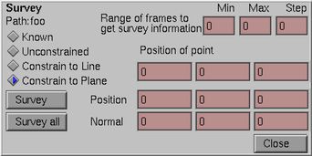
The survey panel is used with 3D tracking to generate the 3D postions of the track points. This can be thought of as the inverse of the camera tracking problem: If you have track a point in many different frames, and have valid camera data for those frames, you can tell where the point is in 3D space.
In the unconstrained case, the camera needs to change position for this to work; you need to have parallax (as you get from binocular vision, or by moving your head back and forth) to determine how far away a point is. On the other hand, if you know the plane, or a line, that the point should lie in, then only one image and camera position is typically necessary to generate a 3D position.
The range of frames to use to determine the points position is specified in the three text-entry fields at the top of the panel. Only frames where the point is valid are used. By default, the whole length of the sequence is used. It is very common to specify a much shorter interval; for example; when you only have valid camera data for the first few frames. Another case would be when you type in an assumed camera position for the first frame, and generate positions for all the points based on just this first frame.
The point can be unconstrained; or to lie along a line or in a plane. In the unconstrained case, the parallax of the moving camera is the only input the program has; but if the camera is moving dramatically that is all that is needed. If you constrain a point to a plane, or especially a line, you eliminate so many degrees of freedom that the position is likely much more accurate. Finally, if the Known button is selected, the survey button is deactivated. This is necessary in the case of Survey all, you don't want points whose positions you are sure of being re-computed.
The position of the point can be typed in to give the program a starting point for its solution. Mostly, though, the position here is used to verify the results of the calculation.
To specify a line, you must enter two points along the line. To specify a plane, you must specify a point on the plane and the plane's normal vector. These are entered in the two sets of three text-input fields.
Hitting the Survey button calculates the position, and enters the result into the Position of point fields.
The Survey all button is currently unimplemented, but it should cycle through all the points and re-calculate their position.
A very common iteration is to calculate the camera position, then re-calculate the position of all the points based on this new camera, then re-calculate the camera based on these better points, and so on. If there are some absolute references, that is, points whose position is known explicitly, this iteration will converge before too long.
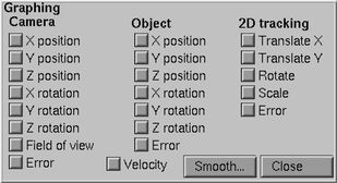
The graph panel brings up a graph viewer with the specified parameters. Each of the three types of generated curves can be displayed. The X position and orientations are displayed red, the Y values are green, and the Z values are blue.
The graphs that are displayed can be scrolled with the middle mouse button. The F1, F2 and F3 keys are used to reset the view, zoom in, and zoom out respectively. Zooming in requires that you drag out a magnification box, it doesn't zoom around the cursor like the image viewer.
The Smooth... button opens a panel that can be used to smooth
out the curves.
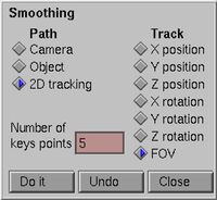
The smooth panel allows smoothing. It's a unique approach to smoothing, so read this carefully.
Select the curve, and the track to smooth. Then, specify the number of key points in a b-spline that will be used to approximate the curve. The best (in a least-squares fitting sense) uniform b-spline that fits the input data is generated.
Perhaps not obviously, if you specify 2, you get a straight line.
If you specify 1 point, then you get a horizontal straight line that is
the average of all the points. Often, I'll use this 1-point feature.
Say I am doing a 3D tracking, and I know that the lens doesn't zoom, but
I don't know what the field-of-view angle is. I can let the program figure
it out for every frame, then replace the calculated values with the average
of them all. Then, back in the 3D window, I'll disable the FOV calculation
and re-calculate all the camera positions.
You are given a set of frames, typically from what is supposed to be a locked off camera, where in fact the image drifts in the frame somewhat. This can be due to film weave (the film not being registered correctly when it is shot or scanned), wiggling of the camera during shooting, or any other reason.
Look at the first frame of the sequence. Find a nice sharp feature, that is easy to see, that exists througout the sequence and is never hidden by anything moving in front of it. This could be the edge of a window, a spot on the floor, it could be anything, as long as it is fairly sharp and has a lot of contrast with the surroundings.
Hit the New button to create a new track point. Place it with the left mouse button over the feature in the image. Now, slide the slider to the last frame, and use the middle mouse button to move the track point over the feature. This will establish this track point throughout the sequence, from beginning to end, and give the program a rough approximation of the motion of that point over the sequence.
Hit the Correlate button. This will bring up a box around the track point. Drag the corners of the box with the middle mouse button to encompass the feature. The bigger the box, the more potential accuracy is possible, but the slower the program will run. Once you are happy with the shape of the correlation window, hit AllFrames <-. This will cause the program to use correlation to position the track point in every frame of the sequence. The program will run happily along, until there is a problem. The only problem that can happen is that correlation cannot find a match in the image of the quality specified. The quality of match is determined by the Maximum average difference value. If the program beeps and stops, observe that the maximum average difference was exceeded, and either adjust the size of the correlation window to get a better match, or increase the allowable error. Then either continue from the current frame, or go back to the beginning. If the pictures are large, and take a long time to read, you can speed this up dramatically with the Subviewport button. Ensure that there is a reasonable margin around the track point, when doing this.
If you are only worried about steadying translation, you might skip this paragraph, but even in that case it is better to have multiple track points. Find a few (say, three or four, if possible) other good tracking points in the image, widely spaced around the screen. Follow the above procedure to track them throughout the sequence, too. Having multiple points has several advantages
Now would be a really good time to hit Write to store the work that you have done.
Finally, you can generate the output frames. The Fast button on the bottom of the image uses a bilinear interpolation, rather than a much better negative-lobe filter, it is about 6 times as fast but noticably blurrier. Choose the option you want, specify a prefix for the output frames, and hit the bottom Generate button to make the steady frames.
3D tracking is one of those many parts of life where preparation is key. Before you shoot the shot, it would be very good to survey the environment. Look for easy-to-track features that are visibile in the room, and measure their positions in 3D, that is, with respect to the floor and two walls. More points are always better than fewer; the more points you have the smoother and more accurate your tracking will be, and the less sensitive to errors due to camera distortion. If there are no good points to track, putting some in would be a good idea; they are relatively easy to paint out later and will make the tracking possible. Remember that ras_track uses right handed coordinates, that is to say, that positive Z is toward the camera, and negative Z goes away from it.
As the shot is filmed, make an estimate of the camera's position; this can be very rough, but it's good to have a reasonable estimate.
Once you get the film (or video) scanned into the computer, track the points in the normal way. For 3D camera tracking, you'll surely find that you can't track points from the beginning of the sequence to the end without trouble, the image will change size dramatically, or rotate, or will be occluded, or something else. Still, persevere. Get as many tracked points as you can for as many frames as you can.
Now, hit the 3D... button. For each point and type in the measured 3D position. This is so tedious and prone to error that I've never seen it done correctly the first time; so be careful and patient, and review your work. Pay particular attention to the signs of the positions that you enter.
For the first frame of the sequence, type in your estimated camera position. It need only be very rough, but the closer the better.
Now, make sure that before you go any further, that you save your work.
Enable every check-box, so that all parameters get calculated. Hit the "Compute one" button. This may take a little while, because the computer will try many guesses the first time to get something to work.
Hopefully, you will get a reasonable solution. Look at the Error: value; if it is small (say, less than 10) you've probably done everything right. Toggle on the Show camera tracking button. Little x's should appear next to or on top of all of your track points; showing the computed 2D position of the points based on the calculated camera parameters.
If you know that the lens is fixed, you might now turn off the Field-of-view angle toggle. Then, hitting Compute All should calculate the camera parameters for each frame very quickly.
Review the data with the Graph... menu. Look at the position curves and the rotation curves. Are they smooth? Are there big jumps anywhere? If there are big jumps, go back and look at those frames to see if something went wrong. Look at the error curve; and see if there are any jumps or discontinuities in that.
Now, you can save the data, and use mp_print to print out a text file of the camera information; by typing (assuming that the datafile is called "track.mp")
mp_print track.mp camera
The track_to_sdl program converts the camera or object motion data in a ras_track multipath file into an Alias Anim SDL file. This can be imported into Alias, to drive the motion of the camera or object.
The usage of the program is as follows:
usage:  track_to_sdl file.mp nodename [-object]
which:  prints an ANIM SDL from a ras_track multipath file
where:  file.mp  is the multipath file
        nodename is the name of the object in the file
        -object  print the object transformation, rather
                 than the default camera transformation
This creates as output a file with the name of the node; this is loaded into Alias after selecting the Persp node in the SDB window and doing an File->Import->Anim menu pick.